Chapter 5: Preparing technicaldocuments
Tetra4D Reviewer can be used to prepare screen captures, diagrams, section views and other graphics to incorporate in technical documents.
It is also possible to prepare exploded views to include in exported PDF files. Users working in Acrobat or Reader® can view and manipulate the 3D data exported as PDFs.
3D markups
About 3D markups
3D markups are entities that appear in the Model Tree, under Annotations, and in the document pane. Like any other entity, you can hide, show, delete, and see properties for individual markups. You can select and edit a markup.
Note: Balloon markups serve different purposes than 3D markups and appear in a different location in the Model Tree. Balloon markups assign numbers to individual parts. These numbers are useful for identifying parts for exploded-view callout captions and the bill of materials.
Creating a 3D markup
 You can attach markups to all types of geometries, such as points, edges, axes, surfaces, and solids.
 If you want to limit your markup to a specific type of entity, change the Selection Filters.
1. Click in DOCUMENTATION tab
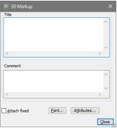
2. Under Title, type the text to appear as the markup label, or leave the Title blank to use the part name as the markup text.
3. Set other options, as needed:
• Type in the Comment area.
Note: Comment text appears only as a tool tip for the markup in the Model Tree and in the markup Properties.
• Click Font and select options for font characteristics.
• Click Attributes and select property information to include in the markup.
•
Important: Be careful to leave the 3D Markup dialog box open. If you close the dialog box before placing the markup in the document pane, no markup is created and your selections are lost.
4. Select the reference entity in the Model Tree or document pane.
5. Without clicking, move the mouse over the document pane to move a preview version of the markup.
Note: As you move the mouse, the reference point snaps to various positions on the selected entity. The preview text position and connector line also change.
6. When the preview 3D markup is in the position you want, click to set it in place.
7. Continue working:
• To create another 3Dmarkup, change the text and options in 3DMarkups, as needed, and select a reference entity.
• To work on a different task, close 3D Markups.
Note: After you click to set the markup position, the markup appears in both the Model Tree and the document pane.
Hide and show 3D markups
Change the visibility of 3Dmarkups:
• To hide and show individual markups, select them, right-click the selection, and choose Hide/Show.
• To hide all 3D markups, Click  in VISUALIZATION tab.
• To show 3Dmarkups, Click in VISUALIZATION tab to deselect it. If any markups remain hidden, select them in the Model Tree and choose Hide/Show from the context menu.
in VISUALIZATION tab to deselect it. If any markups remain hidden, select them in the Model Tree and choose Hide/Show from the context menu.Advanced 3D markups
You can add advanced options and features to markups either as you create them or later, by editing existing markups.
Attach Fixed
The Attach Fixed establishes an uneditable reference point for a markup. As a reminder, the reference end of the connector line appears as an arrow instead of a dot. You can select the Attach Fixed option when you create a markup or later, by editing.
When you create an Attach Fixed markup, your first click sets the reference point. When Attach Fixed is not selected, a preview markup snaps to different positions as you move the mouse over the document pane. When you click, the current preview sets the markup in place.
You can apply the Attach Fixed feature when you create a markup or by editing it later.
Multiple connector lines
You can attach one 3D markup to multiple parts or locations. You can add lines immediately after you create a markup by right-clicking anywhere in the document pane and choosing Add Geometry. Or, you can add connector lines later, by editing.
Bent connector lines
Connector lines can be segmented so that they bend around other displayed items. You can bend lines before you set the final location of the markup by right-clicking anywhere in the document pane and choosing Add Bend Point. Your next click sets the position of the bend point. You can also bend lines later, by editing.
You can add multiple bend points to a connector line.
Comments
Notes you add here appear as a tool tip in the Model Tree and in Properties for the markup.
Comments aren’t part of the markup label.
Font options
You can set font options for new markups in two ways:
• Globally, by changing settings on the Preferences Markup tab.
• Individually, by opening the Fonts dialog box from within3D Markup as you create the markup. You can change font options for existing markups by editing.
Attributes
The Attributes dialog box provides an opportunity to add certain CAD data to the 3D markup label. For example, you can include information about the Modeler or density of a component part. This attribute information in added to Title text you type when you create or edit the markup.
Editing a markup
You can edit the text, the text display, the connector lines, and the position of an existing markup. Editing always begins by selecting the markup.
You can select multiple markups and edit them simultaneously. Simultaneous editing is useful for certain kinds of changes, such as moving markups in the same direction or changing font characteristics.
You can select markups in three ways:
• Expanding the Annotations and Markups structures in the Model Tree and clicking and Ctrl-clicking individual markups.
•  Clicking and Ctrl-clicking the connector line or text of markups in the document pane.
• Click in VISUALIZATION tab, and button Markup.
Note: Simultaneously editing the text of all markups isn’t recommended. The Edit menu has no Undo command. If you change your mind and want to revert to the original text, it would require editing each markup one at a time.
Moving a markup
1. Right-click the selected markups and choose Move.
2. Move the mouse until the markup preview appears in the position you want, and then click to complete the move.
Note: When Attach Fixed is active for the markup, you can move the markup text and change the connector line, but not reference point. To make the reference point movable, too, right-click the markup, choose Edit…, and deselect Attach Fixed.
Editing 3D markup text
1. Right-click the markup and choose Edit….
2. Type text edits in Title and Comment.
3. When finished, click the Close [x] button in the upper right corner.
Note: You can edit the title by double-clicking the markup name in the Model Tree and typing.
Changing font settings for a 3D markup
1 Right-click the markup and choose Edit Markup Font.
2 Change the font options as needed.
Note: You can also open the Font dialog box by clicking Font in the Edit Markup dialog box when you are editing markup text.
Adding a bend point to a markup leader
Bend points create a segmented line so that it can bend around other display items. You can create multiple bend points in a connector line.
1. Click the markup text or line in the document pane to select the markup, or select it in the Model Tree.
2. Choose Tools > Edit Markup.
3. In the document pane, right-click the markup and choose Add Bend Point.
4. Click a position in the document pane to set the bend point position, and thenclick againto set the positionof themarkup.
You can create multiple bends in a line by choosing Add Bend Point again in the context menu.
Adding markup leaders referencing other geometries
Adding geometry means creating multiple connector lines between a markup and the component parts.
1. Click the markup text or line in the document pane to select the markup, or select it in the Model Tree.
2. Choose Tools > Edit Markup.
3. In the document pane, right-click the markup and choose Add Geometry.
4. Click to set the position of the new connector line.
You can create more lines by choosing Add Geometries again in the context menu.
Note: You can also bend the lines as you add geometries, using the right-click Add Bend Point command.
Removing one of multiple markup leaders
1. Select the markup.
2. Choose Tools > Edit Markup.
3. In the document pane, right-click the markup and choose Remove Link.
Balloon notes
About balloon notes
Balloon notes assign numbered balloons to parts. These useful references identify individual parts for the bill of material and in illustrations.
Balloons appear as “Balloon definition” in the Model Tree. Balloons fit under the Configurations
structure, as part of the configuration that was active when you generated the balloons. You can create balloons for locked or unlocked configurations.
 Creating balloons
1. Click in DOCUMENTATION tab, the following dialog box appears:
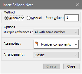 .
2. Select a Method area, select Automatic or Manual, and type a Start Value for the numbering.
3. If appropriate, choose a Multiple References option to handle cases of multiple instance soft he same part.
4. If appropriate, choose an Assemblies option to handle cases in which your selection includes a branch assembly.
5. In Arrangement area, choose how to organize the balloon positions in the document: Classic (each balloon close to the part it numbers), Square, Circle, Top, Bottom, Left, or Right.
Note: You can change the Arrangement later by right-clicking the Balloon listing in the Model Tree.
6. In the document pane or Model Tree, select the parts or assemblies that you want to number.
7. Click Create.
Balloon note options
The Insert Balloon Note dialog organizes related options together.
Automatic and Manual number assignments
You can apply manual and automatic numbering either alone or together.
Manual numbering: Manual numbering is useful when you want to reserve a number or series of numbers for specific parts. In these cases, apply the Manual numbering first. Then apply Automatic numbering to add balloon labels to the unnumbered selected parts.
Automatic numbering: the default starting value is 1, but you can start with any positive integer or zero. Regardless of what value starts the numbering, the increment is always 1 .