Plane
• Sets the direction along a plane that you select in the document pane.
Note: Clicking Select Direction cancels any previous reference items and restarts the process of setting a direction.
Stack up displacements for multiple parts
Stack Up option will simultaneously move multiple parts by different amounts of displacement. The order in which you select the parts determines how far they move. For example, if the first part moves by x amount, the second part moves 2x, the third part moves 3x, and so on.
1.  Click in DOCUMENTATION tab.
2. Select a typeof action, action options, and displacement, as usual.
Note: Stack Upisavailable only for move along axis  rotate around axis
 , rotate with angles
 , and Move with coordinates
 .
rotate around axis , rotate with angles , and Move with coordinates .3.  Select Stack Up .
4. Ctrl-click to select parts, selecting the part you want to move least first. Continue selecting in order of increasing multiples of the displacement.
5. Set the displacement value, and click Apply or OK.
Note: The Stack Up feature is also available for custom animations.
Restore the initial positions of moved parts
After you move one or more parts, you can restore them individually to their previous positions.
Note: If you locked the configuration after moving the part, unlock it. When it is unlocked, you can restore parts to earlier positions.
1.  Select the moved parts.
2. Click in DOCUMENTATION tab.
3. When a message appears asking you to confirm the repositioning, click OK.
Note: If you have moved a part several times, you can only restore the most recent previous position.
Locate entities visually
Complex assembly displays can make it challenging to locate specific parts and other entities, such as markups and balloons.
One method of identifying an entity is to select it. Selecting highlights entities in both the document pane and the Model Tree.
Another method is to use the Focus and Show Me features. These features are especially useful when you want to locate an object without selecting it.
You can also locate an entity by searching it.
Show me (Highlight an entity)
Highlighting draws a red, translucent sphere around the image of the selected entities in the document pane.
1. In the Model Tree, right-click the entity and choose Show Me. Clicking anywhere in the document pane removes the highlight.
Focus on an entity
Focusing does two things: It adjusts the zoom level to the maximum level at which you see all selected entities. It places the center of rotation to correspond with the center of a bounding box for the selected entities.
1. In the Model Tree or document pane, select one or more entities.
2. Right-click a selected entity and choose Focus.
Note: The zoom level and center of rotation set by focusing remain in effect until you change them.
Creating geometric entities
You can generate some simple entities based on existing geometry. For example, you can create a reference point, an intersection, or an axis, or define a new coordinate system.
These entities are permanent and appear in the Model Tree. The location of the entity in the Model Tree and the type of icon appearing with it depend on the entity type. You can use these entities for other operations, such as measuring.
Note: Created entities are not solids or components in the 3D assembly. Physical parts and assembly entities must be created in a CAD application and can be imported into a session file .
 Creating an entity
1. Click in DESIGN REVIEW tab.
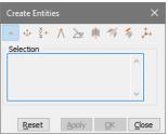
2. Select the type of entity that you want to create.
3. Follow the cues that appear displayed in the status bar at the bottom of the application window to make selections in the documentpane.
4. Create the entity:
• Click Apply to create the entity and leave Create Entities open.
• Click OK to create the entity and close Create Entities.
• Click Close to close Create Entities without creating an entity.
• Reset to deselect and start creating a different entity.
Types of created entities
The Create Entities control window provides tools for creating nine types of entities. These entities are geometrics.
In the same way as with measurement tools, several Create Entities tools ask you to confirm the locations you select. The pointer changes to the Accept/Reject  pointer, indicating that you can right-click to reject the proposed location and see another proposed location.
Creating a point from selection 
• Creates a Point entity at a position you select after selecting this tool.
Creating a point as a center of a circle defined by 3 points 
• Creates a Point entity from three points you select in the document display after selecting this tool.
•
 Creating a point by coordinates
• Creates a point from the values you type in X, Y, and Z, using the CAD coordinates system.
Creating a point as an intersection of segments 
• Creates a point where two selected line segments cross.
Creating a point as an intersection of a face and a segment  .
.• Creates a point where a selected line segment crosses a selected face.
Creating an axis from a cylinder 
• Creates a wireframe entity from the axis of a cylindrical part or entity.
Creating a curve as an intersection of faces 
• Creates intersecting curves from faces that you select.
Creating an entity by extraction  .
.Retrieves information from the selected items as entities under an entity named “[PARTNAME] Extraction.” Extracted entities can be based on any combination of the three Selection options:
• Basis Surface: Generates the original surface for the selected face of the solid or the surface as it was before any trimming operations.
• Face: Generates a copy of the selected face from the solid or the surface.
• Wire: Generates subcurves and characteristic points from a selection of composite curves. Generates original and characteristic curves for a selected face. Original curves refer to trimming curves. Characteristic curves refer to elements such as the axis of a cylinder.
•
 Creating a Coordinates System
Defines a system of coordinates based the selected reference option and elements you select in the document pane. The new coordinates system appears as Axis [#] under the Coordinates System section of the Model Tree.
Options for creating coordinates systems