Arrangement options
• Classic Sets balloons according to the available space so that they are close to parts but
don’t block the view of those parts.
• Square or Circle Sets balloons on a plane along the edges of an imaginary square or circle.
• Top, Bottom, Right, or Left Sets the balloons in a straight line across the top, bottom, left or right of the display.
Editing balloon number
You can change the numbering of individual balloon markups or replace balloon numbers with text. In the Model Tree, double-click the number and type replacement text or numbers.
The size of the balloon adjusts so that it fits around the replacement text or number. Multi-word text doesn’t wrap within the balloon but appears on a single line. The Balloon column in any existing Bill Of Materials updates to show the revised balloon text.
Bill of material
About bills of material
A bill of material (BOM) collects data about selected parts and organizes it in table form. A bill of material is especially useful for checking assemblies and producing technical documents. You determine which parts appear in each bill of material you create.
You can create multiple BOM entities. These entities are named BOM #x, where x is a number representing the order in which you created it. Each new bill of material appears in the Model Tree under the currently active configuration.
Creating a bill of material
1.  In the Model Tree, activate the configuration in which you want to create the BOM.
2. Click in DOCUMENTATION tab
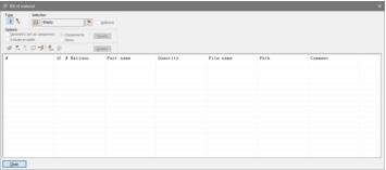
3.  Under Selection, click the selection button to enable the manual selection process.
4. In the document pane or Model Tree, click and Ctrl-click to select elements that you want to include in the bill of material.
5. You can select individual items (parts), components, and assemblies.
6. In the Bill Of Material window, click Create.
Note: The information appears in the table and a BOM #x entity appears under the active configuration in the Model Tree.
Note: You can reopen any bill of material (BOM) entity by double-clicking it in the Model Tree.
Advanced options for bill of material
Settings for creating a bill of material are organized in three areas in the Bill Of Material window.
“Type” options
• Part List Bill Of Material  Includes the selected parts at the item level only, and ignores the assembly hierarchy.
• Hierarchical Bill Of Material  (Requires a selection in the Model Tree, not in the document pane.) Lists according to the Models structure and the selections in the Options area. If Items is selected, small indents in the Part Name column reflect the relationships between assemblies, subassemblies, and components.
•
“Selection” options
• Selection button  Enables you to manually select entities that you want to include in the bill of material.
• Information area Shows the current number of selected elements and identifies them as Groups or Items.
• Detail Level button Determines what elements are included when you select a group. Repeated clicks cycle through three selection levels:
• Group  Lists a selected assembly, subassembly, or component without listing subordinate elements within that group.
• Component  Lists all product definitions (components) in the selected group but does not list the group itself.
• Item  Lists only the individual parts (geometries) in the selected group.
• Balloons Automatically selects all entities with balloon markups. If the active configuration contains no balloon markups, the Balloons option is not available. When Balloons is selected, you can manually edit the parts selection by Ctrl-clicking, as needed.
“Options”
Additional options are available when Hierarchical is selected in the Type area:
• Geometric Set As Component Interprets any geometric sets as hierarchical nodes. (Geometric sets are available as a feature in only some CAD formats.)
• Include Invisible Lists all parts in the selection, regardless of whether they are hidden or
shown. When deselected, hidden parts don’t appear on the list.
• Components Lists structures down to the component level on separate rows. Rows include references to geometric parts.
• Items Lists each individual geometry (item) and product definition (component) on a separate row.
Opening a bill of material
The information for parts is organized in columns. By default, attributes columns are hidden.
1.  If necessary, activate the configuration in which the bill of material appears.
2. Click in DOCUMENTATION tab.
 You can also open a bill of material by double-clicking it in the Model Tree. BOMs appear under individual Configurations listings in the tree structure.
Information provided in a bill of material
The displayed columns appear in the order shown here and with these names:
• Number Value corresponding to the order of the row on the table.
• # Balloon Balloon value for the listed part (if available).
Note: A check box appearsnext to the # Balloon column name when balloons exist for any of the parts. Deselecting the check box hides the balloon numbers in the column but leaves the column open.
• Part name Name of the listed element.
• Quantity Number of instances of the listed part.
• File Name Name of the CAD file corresponding to the listed part.
• File Path Location of the CAD file for the listed part.
• Comments A placeholder column for text notes you add to the bill of material.
• Attribute columns By default, columns for part attributes, such as density, don’t appear in
the bill of material.
Adjusting layout of bill of material
The data and arrangements in a bill of material can be changed like other types of tables.
Change column width
1. Drag the bar next to column name.
 Double-clicking a cell expands the column width so that you can see all the text in that cell.
Rearrange columns
1. Drag the column headings left or right.
Sort table by the data in a column
Sorting arranges the table rows in alphabetic or numeric order for the selected column.
1. Click a column header once to sort the table in ascending order.
2. Click the column header again to sort in descending order.
Show and Hide individual columns
1. Right-click any column heading, and choose Show/Hide Columns.
2. Under Standard, deselect only the columns that you want to hide.
3. Under Attributes, select only the additional columns that you want to include in the bill of material.
1.
Adding notes in a bill of material
1. Double-click inside a Comments column cell, and type any text you want to add.
Note: Your notes are saved with the bill of material. You can edit Comments text by double-clicking a cell and typing.
Updating a bill of material
 Only the Comments text can be directly edited in a bill of material. However, you can update the list with new selections and options.
1. If necessary, activate the configuration with the BOM, and button in DOCUMENTATION tab.
2.  Change settings for the BOM type and hierarchy, as needed.
3. Select the selection button to activate part selection.
4. Select and deselect groups and parts, as needed.
5. Click Update.
Note: Updating removes any text in the Comments column. To keep a record of the comments, choose Create instead of Update. Or, export a reference copy of the BOM before updating.
Interactions between a bill of material and document views
The Bill Of Material includes a toolbar. You can use these tools for interactions between the Bill Of Material window and the parts display.
• Highlight Selected Parts  When selected, parts that you select in the Bill Of Material are also selected and highlighted in the document pane.
• Display Only Selected Part  Hides all parts except those parts that are currently selected in the Bill Of Material.
• Restore State  Reverts to the document pane view in effect when you created or opened the bill of material.
• Always Fit All  Adjusts the document pane zoom to the maximum level that still shows all selected parts. When you select a different part, the zoom adjusts again. (Available only when Display Only Selected Part is selected.)
• Always Display All Instances  Displays all instances of a selected part instead of displaying only that instance of the part. (Relevant only when Always Display Only Selected Parts is also selected.)
• Select In View To Find Item In Current Bill Of Material  When selected, parts that you select in the document are also selected and highlighted in the bill of material.
•
Exporting a bill of material
When you export a bill of material, the resulting file includes all information in the visible columns.
Data in hidden columns isn’t included.
1. With the bill of material open, click Export Bill Of Material  to open the Save As dialog box.
2. Select a location andfilename.
3. In Save As Type, choose a file format: Text Files (*.txt) or HTML Files (*.html).
4. Select additional options for the selected format:
• For a text file, choose separator characters in the Field Separator and Text Separator menus, and click Save.
• For an HTML file, select Automatic Snapshot to include snapshots of all listed parts. Then select an image file format (.bmp or .jpg), and click Save.
Note: The Automatic Snapshot option adds an Automatic Snapshot folder to the location selected for the exported HTML file.
Snapshots
About snapshots
Tetra4D Reviewer provides features to create screen-shots of the 3D area. You determine how much of the image to capture, the resolution, and the format of the saved snapshot file.
Snapshots don’t become part of the session file. You save snapshots externally as independent image
files or by pasting them into a different application.
You control the resolution of snapshots through the Read/Write Image preferences.
Creating and saving a snapshot
1.  Adjust the view as needed, such as changing the orientation, zoom level, background color, and so forth.
2. Click in DOCUMENTATION tab and select the type of snapshot:
•  For BMP, JPEG, and TIFF formats, Click
 or click
 .
For BMP, JPEG, and TIFF formats, Click or click .• For 2D DXF or EMF formats, click .
3. (Only for the Region To Raster method.) Adjust the black outline that appears to enclose the area that you want to capture:
• Drag the corners and midpoints to move the image borders.
• Drag within the outline to move it.
• Click Snap in the Snapshot dialog box when you finish changing the outline.
Note: While you are defining a region, you can zoom with the mouse wheel or by choosing
View > 3D Controls > Fit Visible. Other 3D Controls tools aren’t available.
4. In the Export dialog box, select the file format, filename, and location for the snapshot.
1.
Elements shown and ignored in vector exports
Vector snapshots always include all geometric entities and balloons currently appearing in the document pane. The background color is ignored and replaced with white. Vector snapshots capture geometries in real size.
Vector snapshots ignore any grid displays. In DXF format, dimensions and markups are ignored. In WMF format, dimensions and markups are included.
Copying snapshot to clipboard
1. 
 Adjust the view as needed.
2. Click in DOCUMENTATION tab and click .
3. Paste the image into a document in another application.
Creating a “Quick Snap” image
Quick Snap creates snapshots using the settings for a previous snapshot in the same work session. Consequently, Quick Snap is not available before you export at least one snapshot or immediately after you capture an image to the clipboard.
1. Create and export a snapshot by another method, using the parameters you want to apply to your Quick Snap images.
2.  Adjust the view of the 3D model, as appropriate for the next screen capture.
3. Click in DOCUMENTATION tab.
4. (Only if you used Region To Raster for the original snapshot.) Adjust the size and position of the cropping outline, and click OK in Snapshot.
Note: The Quick Snap capture is automatically named and saved without any notification.
You can continue changing views and taking Quick Snaps. Quick Snap remains available until you close the document.
The Quick Snap capture is saved in the same location as the previous snapshot. Quick Snap applies the same filename as the previous snapshot with an identifying number. For example, if you took a raster snapshot and named it engine.bmp, the subsequent Quick Snap images would be named engine_00.bmp, engine_01.bmp, and so forth.
Set Snapshot resolution
1.  Click in WORKSPACE tab, and click the Read/Write Image tab.
2. Click Resolution.
3. Select a resolution:
• Select Window to use the current resolution of the document window.
• Select Desktop to use the screen resolution set on the Settings tab of the Display properties Control Panel.
• Select the numeric option and choose a resolution from the menu of resolutions supported by your computer graphics board.
• Select Custom and enter Width, Height, and DPI values.
•
Note: When DPI is selected, a second set of Width and Height options are available. The pixel values define the dimensions of the snapshot image.
Note: Settings changed in the Preferences remain in effect until you change them again. If you select a high resolution and want to go back to a default resolution setting, use the Read/Write Image preferences to reset the resolution.
Advanced resolution options
The pixel values for Height and Width determine the actual size for image output. If DPI is selected, the DPI and pixel values are used to calculate the print size of the snapshot. The Height (mm) and Width (mm) describe that print size.
If you change the DPI or a height or width dimension, other values are automatically recalculated. These changes appear after you press Tab or click to advance to another option in the Resolution dialog box.
For example, changing the Width (pixels) value automatically changes the Width (mm) value. Changing the DPI value automatically changes both the Width (pixels) and Height (pixels) values. However, changes to a Width value don’t affect Height values.
Exploded views and Animations
About exploded views and animations
Animations show individual parts or groups of parts in action. Animations can be simple or complex, multi-step actions. Animations can show all or selected parts in motion and changes in visibility .
Animations are associated with the active configuration at the time of their creation. You can create animation only when the active configuration is unlocked.
Built-in features create exploded views in a minimal number of steps. You can create other simple or complex custom animations one action at a time. Animations are saved with the session file and can be exported in AVI format or within a PDF.
Creating an exploded view
 An exploded view shows the component parts separated from each other around a central point. Exploding moves each part in a separate action. You can rearrange the action sequence and add other actions by editing the animation after you create it.
1. Click in DOCUMENTATION tab:
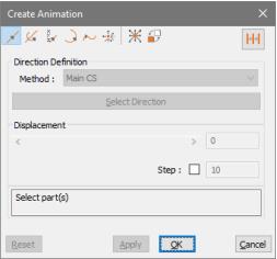
2. Select Explode  in the Create Animation controls window.
3. In the Model Tree or document pane, select the assembly or specific parts that you want to separate in space.
4. Select options, as needed:
• Hierarchical Moves assemblies and parts in the order that they appear when the Models structure is fully expanded. The first assembly on the list moves first, followed by the first subassembly under that assembly. Next, any tiers under the first subassembly move, and so forth.
• By Level Moves assemblies and parts by tier levels. All assemblies at the top tier explode first, starting at the top of the Model Tree structure. Next, all second-tier subassemblies move, in the order that they appear in the Model Tree. Then all third-tier structures move, one at a time, and so forth.
•
• Project Path Keeps actions parallel to the Main CS. Displacement slider Controls the amount of movement for parts. Level Limits the number of structural tiers that move.
5. Finish the animation:
• Click Apply to set the first action of the animation and continue adding more actions.
• Click OK to save the animation with just the exploded view action.
Expanding and collapsing exploded views
You can show or reverse an exploded view as a single-step change.
1. In the Model Tree, activate and open the configuration containing the exploded view.
2. Right-click the exploded view and choose the available command:
• Compact To collapse the exploded view.
• Expand To expand the exploded view.
Hiding or showing paths
By default, blue lines appear in the document pane to show the travel distance and direction of animated parts. You can hide or show these lines.
In the Model Tree, right-click the animation and choose Hide Path or Show Path.
Creating animations with custom actions
Actions are individual movements or visibility changes in an animation. Several methods of defining movements are familiar techniques used to move parts in the document pane.
1. In the Model Tree, activate the configuration in which you want to create the animation.
 Note: You can create new animations only in unlocked configurations. If you lock the configuration after creating an animation, you can edit the animation without unlocking the configuration.
2. Click in DOCUMENTATION tab.
3. Select an action type for the first action, using the buttons across the top of the window.
4. In the Model Tree or document pane, select the parts that you want the first action to move.
5. Select the appropriate options for the action type, and review the preview results in the document pane.
6. Click Apply to define the final state for the action.
7. Repeat the process to create more actions, using your choice of methods, options, and parts.
After you create an animation, you can set cameras in the Play Animation controls window. Cameras change the point of view as the animation plays.
Types of action
• Move Along Axis  Moves parts in a straight line that you specify in Direction Definition.
• Rotate Around Axis  Turns parts around a line that you specify in Direction Definition.
• Move With Coordinates  Displaces parts by specific values for the X, Y, and Z axes.
• Move On Helix  Combines movements along and around a line that you specify in Direction Definition.
• Move On Curve  Moves parts along an exact-geometry curve that you select in the Model Tree. Or, moves along a selection in the document pane that is either the edge of a surface or a face of asolid.
• Moving Box  Moves with the Drag & Drop controls. Multiple changes made with different controls can apply to a single action.
• Explode  Separates parts in space around a central point.
• Hide/Show  Toggles the visibility of selected parts.
Options for custom actions
The options that appear vary according to the selected type of action. Options are available only after you select the parts for the action.
• Stack Up  Stack Up creates a separate action for each part you select. The parts move by successive multiples of the displacement setting.
Note: The order in which you select parts determines how far and in what order they move. For example, if the first part moves by x amount, the second part selected moves 2x, the third part selected moves 3x, and so on.
The actions occur in the reverse order that you selected the parts. For example, if you create a Stack Up animation with four selected parts, part #4 moves first. Part #3 moves next, and so on.
Note: Stack Up is available only for Move Along , Rotate Around Axis , and Move With Coordinates action types.
, Rotate Around Axis , and Move With Coordinates action types.• Displacement sliders Move selected parts, either by linear displacement or rotation. Two methods have multiple sliders:
• Move On Helix The upper slider sets the translation (linear displacement). The lower slider sets the rotation angle.
• Move With Coordinates Each of the three sliders sets the displacement along a specific axis of the Main CS.