From CS
• Creates a copy of the selected coordinates system.
Naming rule for created entities
Tetra4D Reviewer assigns default names to created entities. The default name varies with the type of entity created. Some names include a number that indicates the order in which it was created.
Numbers in parentheses following the entity name indicate how many individual entities are included in the created item.
Different created entities can have identical names. You can rename entities to make it easier to tell them apart, as needed.
Operating with the model in the 3D window
About 3D controls in the 3D window for the document
You adjust the visualization of the 3D entities using 3D Control tools, which are accessible in the HOME tab.
The selected 3D tool determines what happens when you drag the mouse within the 3D window.
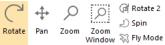
Rotate the 3D model
This control rotates the model around a specific point in the 3D window. The Rotate tool is active by default.
1.  Click in HOME tab.
2. In the document pane, set the center of rotation:
• Drag from any position in the background to rotate around the center of a bounding box that encloses all visible parts.
• Drag from a position on a component to rotate around that starting point, as indicated by across hair  that appears.
Lock a rotation axis
By default, the rotation can be performed freely around any axes.
1.  Click in HOME tab.
2. Using the right mouse button, start dragging to rotate the 3D objects.
3. As you drag, press the spacebar repeatedly to lock a specific axis:
• One time Locks the X axis.
• Two times Locks the Y axis.
• Three times Locks the Z axis.
• Four times Unlocks all axes so that you can rotate freely around any axis.
A double arrowhead in the View CS display in the lower left corner of the document pane appears as a reminder of the locked axis. The axis remains locked after you stop dragging, even if you activate a 3D Controls tool.
You unlock all axes by repeating this process, pressing the spacebar until no axis has a double arrowhead.
Set a fixed center point for rotating and spinning
By default, the center of rotation is automatically set as the center point of the bounding box calculated including all the visible entities.
You can set a different center of rotation that does not change as you manipulate the view in different ways.
 You can set a fixed center of rotation at any position on any part but not on the background or in empty space between parts.
1. Click in HOME tab.
Note: The Rotation Center tool is available only when one of the Rotate tool or Spin tool is active.
2. Click a point on one visible part that you want to serve as the center of rotation.
Note: A white cross hair marks the position in the display, even if you switch to a different type of tool.
3. Drag to spin or rotate the 3D object.
 Note: Notice that the Rotation Center tool remains active as you work, even if you switch back and forth to the r 3D Controls tools.
4. Push again to cancel the fixed center.
Spin a 3D model
Spinning rotates in relation to the Z axis of the View CS. It is especially appropriate for turning images set on a fixed horizontal plane, such as buildings.
1.  Click in HOME tab.
2. Drag in the document pane.
Pan horizontally and vertically
 Panning changes the position of the 3D objects in the 3D window while keeping the orientation.
1. Click in HOME tab.
2. Drag the 3D object left, right, up, or down.
1.
Zoom in and zoom out
Zooming in enlarges or shrinks the view in the document pane.
Zoom in or out
1.  Click in HOME tab.
2. In the document display, drag up to zoom in and drag down to zoom out.
Note: Clicking the Zoom tool and dragging horizontally do not change the zoom level.
 If your mouse has a wheel button, you can zoom without selecting the Zoom tool. Instead, turn the wheel forward and backward to change the zoom level. Wheel-button zooming centers around the current pointer position in the document pane.
Zoom window
1.  Button in HOME tab.
2. In the document display, draw a rectangle to define the zoom area.
 You can switch temporarily to the Zoom Window tool by holding down Shift and dragging. When you stop dragging and release the Shift key, the previously active tool is reinstated.
Fit the 3D model into the display
 The Fit Visible feature shows the model at the maximum magnification that keeps all visible components in the document pane window.
1. Click in HOME tab.
 Double-clickingthe document display with any tool also changes theview to Fit Visible. In some contexts, you can right-click and choose Fit Visible to show all visible parts.
Activating document views
Tetra4D Reviewer offers several features to change views.
• Default views Align 3D objects in various orientations to the axes of the active view coordinates system (View CS).
• Camera Aligns the view in relation to a selected element in the geometry.
Configurations bear a similarity to default views in that they quickly shift the view. You can create custom configurations, lock or unlock them, and use them in later work sessions.
Set a default view
 Applying a default view leaves the zoom level and other viewing characteristics unchanged. The default views appear both on the Views menu and in the Default Views toolbar.
1. Click in HOME tab, and one of the following:
• Top, Front, Back, Bottom, Left, or Right: Sets the view normal based on the active View CS.
• Iso Sets the 3D objects in a standard isometric view, based on the active View CS.
 The Smooth Transitions preferences can help you visualize how the view changes. Selecting these preferences animatesthe3Dobjectsasyouapplybuilt-in views. If these preferences are deselected, the view changes in one step.
Set the camera
A camera setting refers to a combination of zoom level and orientation. Some camera settings are independent entities. Other camera settings change the view according to the entity that is currently selected.
1. If appropriate, select one or more entities.
 Set the appropriate Selection Filters for the type of selection you want to make, such as a curve, face, or axes.
2.  Click in HOME tab, then click
 and choose one of the following settings:
Click in HOME tab, then click and choose one of the following settings:• From Selection Aligns the view to the currently selected entity or to the next entity that you select.
• Restore Config. View Resets the orientation to either the initial settings for the current configuration or the initial view when the file opened.
• From Curve/Edge Sets the view perpendicular to the next curve or edge that you select.
• From Face Sets the view parallel to the next planar face that you select. Or, if the face is not planar, sets the view normal to the face at the point that you select.
• From Coordinate Axis Sets the view perpendicular to an axis (X, Y, or Z) that you select next.
• Flip Rotates the view to the opposite side of the assembly or part.
•
Saving views as configurations
About configurations
A configuration is a view of a 3D model. A configuration includes basic characteristics, such as zoom level, orientation and positions of the 3D objects, visibility of entities, lighting, and background color. Configurations also apply specific types of features created in that configuration. These features include bills of material, balloons, and sections.
When you start a Tetra4D Reviewer session or open a new document, the default, Initial Configuration, is active. Unless Initial Configuration is locked, objects open as they appeared at the end of your most recent work session.
Creating a configuration
1.  Adjust the orientation, zoom level, visibility settings, and other characteristics for the view, as needed.
2. In the Model Tree, right-click Configuration and choose Add Configuration, or click in DOCUMENTATION tab.
3. Type a name for the new configuration. The saved view becomes the active configuration.
Activating a configuration
1. 
 In the Model Tree, right-click the configuration and choose Activate Configuration.
 You can also use the buttons and to step through configurations, or just double-click a configuration in the Model Tree to activate that view.
Renaming a configuration
1. In the Model Tree, right-click the configuration and choose Rename.
2. Type a new name.
Deleting a configuration
1. In the Model Tree, select the configuration.
2. Click Delete from the context menu, or press Delete key.
1.
Locking or unlocking an existing configuration
1. In the Model Tree, right-click the configuration and choose Lock or Unlock.
About locked configurations
When a defined configuration is active and unlocked, any changes to the zoom level, orientation, and so forth, are incorporated into the configuration definition. Locking a configuration prevents changes from altering the configuration definition. Each configuration is individually locked and unlocked. You can lock the default Initial Configuration and custom configurations.
You can change the zoom, rotate, hide parts, and make other view adjustments when a locked configuration is active. When you switch to a different configuration and then back to the locked one, the locked configuration appears in its original state.
Some features are disabled or can’t be applied to a locked configuration:
• Positioning tools
• 3D Markups
• Animation controls
Locking a configuration doesn’t affect your ability to create balloons and bills of material in that
configuration.
Hiding and showing entities by layers and filters
Layers and filters are CAD structural features created within certain file formats. When the CAD file is imported into Tetra4D Reviewer, the filters and layers are imported too. You can’t modify the filters and layers in Tetra4D Reviewer.
However, you can use them to select parts or to change the view of the 3D objects.
The Model Tree for a part on a hidden layer isn’t colored and includes a funnel shape  . The icon
serves as a reminder that you can’t use the ordinary Hide/Show command to display the part.
 Hiding and showing parts by layers
1. Click in VISUALIZATION tab
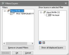
Note: Immediately after the Filters/Layers window opens, you can click Remove Unused
Filters to remove the filters that don’t refer to any layer.
2. Select and deselect layers until only the layers you want to appear are selected, using any combination of methods:
• Click the layers check boxes to select and deselect individual layers.
• Select Filters in the left pane to select layers associated with that component part or assembly.
• Click Select All  to select all layers.
• Click Unselect All  to deselect all layers.
• Click Show Layers in Selected Filter to select layers currently displayed in the document pane.
3. Click Preview, and review the results of your selection in the document pane and Model Tree. If necessary, adjust your layer selections and click Preview again until you are satisfied with the results.
Note: The Preview is temporary. If you close the Filters/Layers dialog box without clicking OK, the view resumes its previous condition.
Showing a part on a hidden layer
The usual Hide/Show command doesn’t affect the visibility of parts on hidden layers. Layer visibility
 can be reversed only in the Filters/Layers dialog box.
1. Click in VISUALIZATION tab.
2. Select the layer that includes the part you want to bring out of hiding.
3. Click Preview to confirm the layer visibility settings, make any adjustments, and click OK.
1.
Fly through mode
Activating the Fly through mode
1. Click  in HOME tab.
2. Press and hold the following keys to control Fly Mode direction and speed:
• Q and D Move left and right
• Z and S Move up and down, left and right (parallel movement without rotation)
• A and E Rotate left and right
• R and F Forward and backward.
• Spacebar Stop movement.
Note: You can also use your mouse to move up, down, right, and left. Use the center mouse wheel to increase and decrease Fly Mode speed.
3. Release the key to stop the fly through motion. You can also use the mouse wheel to increase and decrease fly through speed.
To see a complete list of keys to use in Fly Mode, open the Preferences dialog box, and click the Fly Through tab.
To exit Fly Mode, press ESC or right-click in the model and choose End Fly Mode.
Managing Fly through mode views
With Fly Mode, you can view a model at different angles and magnifications. You can save these views, or positions, to use later. You can also constrain Fly Mode movement to a horizontal plane so that altitude doesn’t change as you move. This feature is useful for moving through architectural models.
Saving a Fly through position
1. In Fly Mode, position the model as you want to save it.
2. Right-click the model, and then choose Position > Store Current Position.
3. Type a name of the position in the dialog box, and click OK.
Modifying a saved position
After you create a position, you can rename it, activate it, or delete it.
1. Right-click inside the model and choose Position > User Positions.
2. Select a user position, and then select what you want to do with the position.
3. Click Close.
Returning to the default position
The default the position in Fly Mode is <Automatic> and always corresponds to the Isometric view.
1. In Fly Mode, click in the document pane, and then right-click in the model.
2. Choose Position > Activate Default Position.
1.
Setting a reference plane for Fly through
You can set a horizontal reference in Fly Mode to retain the same height as you move through a model. This feature is called walk through mode. Altitude doesn’t change in walk through mode. Note: You can change the default height and reference plane settings on the Fly Through tab of the Preferences dialog box.
1. In Fly Mode, right-click inside the model.
2. Choose Reference, and then select the reference type to use:
• Plane Uses a horizontal plane as the reference point. The camera position is constrained to the reference plane and the height is specified in the Fly Through preferences.
• Main UCS Uses the main coordinate system to define a new reference. When selecting this option, the reference plane is the one that is perpendicular to the active axis (X, Y, or Z). The camera is located at the specified height, which is constant.
• Curve or Axis Constrains movement to the length of the curve. The axis is selected automatically by selecting a cylinder face. For an axis or line, you can move anywhere using the keyboard controls (except A and E).
• Free Deactivates the previously set reference and restores default Fly Mode behavior.
• Invert Direction When Plane of Main UCS is used, Invert Direction changes the orientation of the reference to be opposite the current orientation.
Changing the reference plane
1. In the Preferences dialog box, click the Fly Through tab.
2. In the walk-through section, do the following:
• To change the height of the horizontal plane, set the height value and corresponding measurement unit.
• To hide the reference plane, clear the Display Plane option in the walk-through section.
Restoring the original reference plane
Apply a horizontal reference plane to restore an initial state.
1. In Fly Mode, click in the document pane and then right-click inside the model.
Note: The model position remains the same, but the direction moves horizontally.
2. Choose Horizontal from the context menu.
1.
Graphic rotation controls
The graphic rotation controls are displayed in the lower-left corner of the model. Use the graphic controls for quick access to user-defined positions and rotation functions.
1. In Fly Mode, right-click a part of the model to be the reference point for the rotation. The graphic rotation controls are displayed in the lower-left corner of the model.
2. Select a control to change the view of the model:
• Click the triangle to view a list of user positions, and then select a position from the list.
• Click a square to make a 90-degree rotation around the reference point selected in step
1. For example, click the right square to make a 90-degree rotation around the vertical axis to the right. Click the same square again to turn around the model, keeping the same reference point. The back square displays the back view of the model.
Note: The squares are visible only when the mouse is over a model part when you right-click. The point at which you right- click is used as the center of the rotation.
Defining a target point for Fly through
In a complex assembly, defining a target point keeps the focus on that point as you move through the model. When defining the target point, the current position is used as the starting point. The final position is the target point.
1. In Fly Mode, right-click inside the model, and choose Target Point.
2. Select a point on the model.
Note: The red beam represents the distance between the two points.
3. Right-click in the model, and then click Play.
4. Press and hold the rotation keys A and E to move the model.
Note: Use the controls to define the speed and camera orientation. The camera follows the red beam, but the view direction can vary. When the target point is reached, the movement stops.
5. To stop the movement, do one of the following:
• Right-click in the document pane, and then choose Reference > Free.
• Define a new reference.
• Define a new target point, and make an empty point selection (by clicking in an area of the window where no part is displayed).
Note: Because the starting point is fixed, you cannot change the height and the lateral position of the rotation. The Fly Mode direction keys Z, S, Q, D are not active.